Why IGBT Losses at 25 °C Can Lead to the Wrong Heatsink
With losses taken at 25 °C, this 6 kW converter gets a heatsink almost twice too small. A SIMBA electro-thermal study.
Abstract
Sizing an IGBT heatsink from losses calculated at 25 °C can be dangerously optimistic.
In this 6 kW buck converter, a 25 °C loss budget allows a heatsink thermal resistance of 0.97 K/W. When semiconductor losses and junction temperatures are solved together, the actual limit for a junction at or below 125 °C is only 0.51 K/W.
Even losses calculated at 100 °C are not enough: they allow 0.59 K/W, with which the junction settles at 137 °C, 12 K above the limit.
The reason is the feedback between junction temperature and switching losses: in this example, the IGBT switching loss grows by 0.24 W per kelvin. This study uses SIMBA to quantify that feedback and find the correct heatsink limit, and shows how to reproduce the whole analysis in Python.
Key results (design limit Tj ≤ 125 °C) - Coupled electro-thermal limit: 0.513 K/W. - Losses taken at 25 °C: 0.966 K/W allowed, junction far beyond the 150 °C rating (about 208 °C, extrapolated). - Losses taken at 100 °C: 0.593 K/W allowed, junction at 137 °C. - Losses taken at 125 °C, the limit itself: 0.506 K/W allowed, junction at 124 °C.
1. The Problem: Losses Set the Temperature, the Temperature Sets the Losses
Heatsinks are often sized in three steps: compute the semiconductor losses at one junction temperature, add the junction-to-case and case-to-heatsink resistances, then choose the heatsink so that losses × thermal resistance stays below the allowed temperature rise.
The method is fast, but it assumes that the losses used in the first step are those of the temperature reached in the last one. They are not: IGBT turn-on and turn-off energies and diode reverse recovery all grow with junction temperature [3, 5], so the losses rise with it, and the junction temperature rises with the losses. Application manuals warn about it and recommend computing losses at a high junction temperature, or iterating [3, 4].
How much does that matter in practice? This article measures it on a complete converter model.
2. The SIMBA Test Case: a 6 kW Electro-Thermal Buck
The study uses the official SIMBA design example DC-DC Buck-Chopper (Thermal) [1], shown in Figure 1 (see also the thermal modelling tutorial). Only the heatsink thermal resistance (and, in Section 3, the ambient temperature) is changed.
 Figure 1 – SIMBA electro-thermal model of the example: electrical circuit (blue), gate command (green) and thermal network (orange), as shipped (Rheatsink = 0.1 K/W, ambient 25 °C).
| Parameter | Value |
|---|---|
| Input voltage, switching frequency, duty cycle | 600 V, 10 kHz, 0.5 (open loop) |
| Output filter, load | 1.2 mH, 100 µF; 15 Ω (about 20 A, about 6 kW) |
| Devices | IGBT and diode thermal data shipped with the example (labelled Infineon IGW25T120), loss tables at 25 °C and 150 °C |
| Junction-to-case resistances | 0.65 K/W (IGBT), 1.0 K/W (diode) |
| Heatsink | Rheatsink to a 25 °C ambient, swept from 0.05 to 1.4 K/W |
Each SIMBA transient run stops when its steady-state detection triggers, with the heatsink temperature rise still 1.2 % to 2.3 % below its final value. Because the loss laws of the model and its thermal network are linear (Section 3), the final equilibrium is computed exactly from SIMBA's own loss laws and thermal resistances (two linear equations, one per junction); the SIMBA runs, shown on Figure 3, sit 0.3 °C to 1.6 °C below it wherever the junction stays below 150 °C.
3. IGBT Switching Losses Rise With Junction Temperature
To isolate the effect of temperature, we ran the converter with an almost ideal heatsink (0.001 K/W) and swept the ambient from −15 °C to 135 °C: the junctions sit at known temperatures while the electrical operating point stays the same.
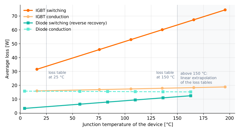 Figure 2 – Average losses of each device versus its own junction temperature, same operating point. Outside the 25–150 °C range of the loss tables (grey area, and the two points below 25 °C) the values are a linear extrapolation. One run (10 °C ambient) had not reached thermal steady state and is not used in the fits.
| Component | Change per kelvin | At Tj = 25 °C | At Tj = 125 °C | At Tj = 150 °C |
|---|---|---|---|---|
| IGBT switching | +0.239 W/K | 33.7 W | 57.6 W | 63.6 W |
| IGBT conduction | +0.016 W/K | 16.1 W | 17.7 W | 18.1 W |
| Diode switching (recovery) | +0.058 W/K | 4.5 W | 10.3 W | 11.7 W |
| Diode conduction | −0.004 W/K | 15.7 W | 15.3 W | 15.3 W |
| Total | 70.0 W | 100.9 W | 108.6 W |
Totals are computed from unrounded values.
The IGBT switching loss rises from 33.7 W at 25 °C to 63.6 W at 150 °C, almost ×1.9, while conduction losses barely move: at this operating point, the temperature sensitivity of the converter is essentially that of its switching energies. For this SIMBA model, because the loss tables are linearly interpolated between the 25 °C and 150 °C data sets, the losses are linear in junction temperature; a real device follows its own, generally non-linear, curve between those points.
4. What This Does to Heatsink Sizing
The design question: what is the largest heatsink thermal resistance that keeps the IGBT junction at or below 125 °C, a 25 K margin below its 150 °C maximum rating?
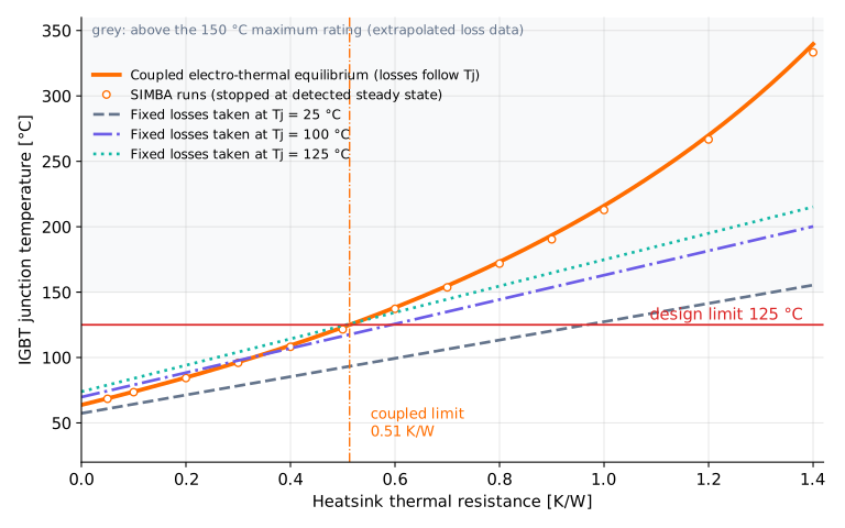 Figure 3 – IGBT junction temperature versus heatsink thermal resistance. Orange line: coupled electro-thermal equilibrium (losses follow Tj); circles: SIMBA runs. Dashed, dash-dot and dotted lines: the same thermal network fed with losses frozen at 25 °C, 100 °C and 125 °C. Grey: above the 150 °C rating, extrapolated loss data.
| Loss budget taken at | Budget losses | Allowed heatsink | IGBT junction with that heatsink (coupled) | Diode junction |
|---|---|---|---|---|
| Coupled electro-thermal | follow Tj | 0.513 K/W | 125 °C | 100 °C |
| 125 °C (the limit) | 100.9 W | 0.506 K/W (×0.99) | 124 °C | 100 °C |
| 100 °C | 93.2 W | 0.593 K/W (×1.16) | 137 °C | 111 °C |
| 75 °C | 85.5 W | 0.695 K/W (×1.35) | about 154 °C (extrapolated) | 126 °C |
| 25 °C | 70.0 W | 0.966 K/W (×1.88) | about 208 °C (extrapolated) | about 174 °C (extrapolated) |
- A "warm" reference is not enough. Losses taken at 100 °C, below the temperature finally reached, give a heatsink 16 % too resistive and a junction 12 K above the design limit. This result lies entirely inside the range of the loss data.
- A 25 °C budget is not a small error. It accepts a heatsink with almost twice the allowed thermal resistance, and the junction would leave the rated range of the device.
- Losses taken at the limit temperature give a safe answer: 0.506 K/W and 124 °C, slightly conservative because the diode is evaluated at 125 °C while it runs at 100 °C.
5. Why Coupled Electro-Thermal Simulation Matters
The loop is simple: Tj ↑ → switching losses ↑ → dissipated power ↑ → Tj ↑. It amplifies every temperature rise. At the 0.51 K/W design point, the IGBT junction rises 46 % more above ambient than a 25 °C budget predicts with the same heatsink (22 % more at 0.05 K/W). Anything that adds losses (a higher ambient, a higher load) or weakens the heatsink (fouling, a higher interface resistance) is amplified by a similar factor, so margins taken on the heatsink alone are consumed faster than a fixed-loss calculation suggests.
This is a positive electro-thermal feedback, which can lead to thermal runaway if the temperature sensitivity of the losses becomes large enough: runaway means that each watt added raises the temperature enough to add more than a watt, and that no equilibrium exists. In this example the feedback stays well below that point: with the loss laws of Section 3, an equilibrium exists up to a heatsink of about 2.8 K/W, far beyond the swept range and the loss data.
A spreadsheet iteration can reproduce the coupled result once the temperature-dependent loss laws are known: start at 25 °C, compute the losses, then the temperatures, then the losses again. Run on the laws of Section 3, it converges to the same equilibrium within 0.01 °C. The difficulty is obtaining those laws for the actual converter waveforms. The point of coupled electro-thermal simulation is not simply to calculate a temperature: it removes the artificial separation between the calculation of the losses and the temperature those losses create. SIMBA computes the switching events, the losses and the junction temperatures in the same run, so changing the load, the switching frequency or the device does not require rebuilding the thermal calculation by hand; the same approach applies to inverters.
6. Reproduce It With SIMBA, Python and an AI Agent
The whole sweep is a loop over the public SIMBA Python API [2]. This code runs exactly as printed with SIMBA 2026.07.22:
from aesim.simba import DesignExamples

for r_hs in [0.05, 0.1, 0.2, 0.3, 0.4, 0.5, 0.6, 0.7, 0.8, 0.9, 1.0, 1.2, 1.4]:
    example = DesignExamples.Buck_Thermal_Tuple()                # .Item1 = design, .Item2 = IGBT/diode thermal data
    design = example.Item1
    design.Circuit.GetDeviceByName("Rheatsink").Value = r_hs
    job = design.TransientAnalysis.NewJob()
    job.Run()                                                    # stops at the detected steady state, 0.3-1.6 °C below the exact equilibrium
    tj = list(job.GetSignalByName("IGBT1 - Junction Temperature (°)").DataPoints)[-1]
    p_sw = list(job.GetSignalByName("IGBT1 - Average Switching Losses (W)").DataPoints)[-1]
    print(r_hs, round(tj, 1), round(p_sw, 1))
The curves of Section 3 use the same script with Rheatsink = 0.001 and the ambient source swept (design.Circuit.GetDeviceByName("Tamb").Temperature). More examples are in the simba-python-examples repository.
For this article, the automation itself was performed by an AI agent connected to SIMBA through the SIMBA Assistant MCP server: it found the official example, wrote and ran the scripts, read the loss and temperature signals and drew the figures with the Python shipped with SIMBA. All numerical results were then recomputed by independent check scripts written by a separate AI review agent (energy balance of every run, exact equilibrium versus an independent fixed-point solver, every number of the text from the raw data), over four review rounds, and the article was reviewed by the SIMBA team. The scripts run the same way without an agent.
7. Limitations
The method does not depend on these assumptions; the numbers do:
- one operating point (600 V, 10 kHz, 20 A, duty cycle 0.5) and a 25 °C ambient, optimistic for a closed enclosure;
- loss tables at two temperatures only, linear extrapolation above 150 °C, no leakage current;
- in the example data, the 150 °C IGBT switching-energy tables are the 25 °C tables scaled by almost constant factors (about ×1.45 at turn-on, ×2.10 at turn-off): the 0.24 W/K slope and every number that depends on it come from these factors, so check them against your own datasheet;
- constant junction-to-case resistances and no case-to-heatsink interface resistance: with the same model, 0.1 K/W under each device brings the limit from 0.513 to 0.439 K/W, and 0.2 K/W to 0.364 K/W;
- the IGBT turn-on energy is read at the IGBT junction temperature, while the diode, whose recovery drives part of it, is about 25 K cooler.
Practical Rule
Practical rule If you size a heatsink with fixed losses, evaluate the semiconductor losses at least at the junction-temperature design limit, not at 25 °C or at a "typical" warm value. As long as the losses rise with temperature, this is conservative (here 0.506 instead of 0.513 K/W). Where switching losses depend strongly on temperature, verify the final heatsink with a coupled electro-thermal model.
8. Conclusion
A loss budget is only valid at the junction temperature it was computed for, and that temperature is the result of the heatsink choice. In this 6 kW IGBT buck, a budget taken at 25 °C accepts a heatsink 1.9 times too resistive, and a budget taken at 100 °C still leaves the junction 12 K above the 125 °C limit. Taking the losses at the limit temperature works; solving losses and temperatures together gives the exact limit, 0.51 K/W here, and the sensitivity of the design around it. For switching-dominated converters, use the coupled answer as the reference and the fixed-loss calculation as the quick estimate that has to agree with it.
FAQ: IGBT Heatsink Sizing and Junction Temperature
Should IGBT losses be calculated at 25 °C or at the maximum junction temperature for heatsink sizing?
At the junction-temperature design limit, at least. In a SIMBA electro-thermal study of a 6 kW IGBT buck converter limited to 125 °C, losses taken at 125 °C allow a heatsink of 0.506 K/W, close to the 0.513 K/W of the coupled model; losses taken at 25 °C allow 0.966 K/W, almost twice the allowed thermal resistance. Taking losses at the limit is conservative as long as they rise with temperature; verify the final choice with a coupled electro-thermal model.
How do you calculate the maximum heatsink thermal resistance for an IGBT?
With fixed losses evaluated at the design limit: R_hs,max = (Tj,limit − Ta − P_IGBT × Rth,jc) / (P_IGBT + P_diode), for an IGBT and its diode on one heatsink, with Tj,limit kept below the maximum rating. An interface resistance under each device is added to its Rth,jc; an interface shared by both is subtracted from R_hs,max. Check the diode junction the same way. In a SIMBA study of a 6 kW IGBT buck (Tj,limit = 125 °C, Ta = 25 °C, Rth,jc = 0.65 K/W, losses taken at 125 °C: P_IGBT = 75.3 W, total 100.9 W), this gives (125 − 25 − 48.9) / 100.9 = 0.506 K/W, versus 0.513 K/W with losses and temperatures solved together.
Do IGBT switching losses increase with junction temperature, and by how much?
Yes: the turn-on and turn-off energies and the diode reverse recovery grow with junction temperature. In a SIMBA study of a 6 kW buck (600 V, 20 A, 10 kHz), with the device data of the SIMBA example (labelled IGW25T120), the IGBT switching loss rises from 33.7 W at 25 °C to 63.6 W at 150 °C, about 0.24 W per kelvin. That slope comes from the example's 150 °C tables; check the switching energies of your own device datasheet.
Why use coupled electro-thermal simulation instead of a spreadsheet for heatsink sizing?
Because losses and junction temperature depend on each other. In a SIMBA study of a 6 kW IGBT buck, the junction rises 46 % more above ambient at the design point than a 25 °C loss budget predicts. A spreadsheet iteration reproduces the result within 0.01 °C once the temperature-dependent loss laws are known; a coupled simulation evaluates the device loss tables on the real waveforms at the junction temperature it computes, in the same run, so changing the load, frequency or device needs no rebuilt thermal calculation, as long as the device data cover the temperatures reached.
Can an AI agent run power-electronics circuit simulations?
Yes. SIMBA Assistant, an optional SIMBA module, includes the SIMBA MCP server, through which an AI agent can edit parameters, run simulations and write Python scripts. A SIMBA study of a 6 kW IGBT buck converter was run that way: an AI agent swept the heatsink from 0.05 to 1.4 K/W in SIMBA through Python, every number was recomputed by check scripts written by a separate AI review agent, and the SIMBA team reviewed the article.
Appendix: Detailed Results Along the Heatsink Sweep
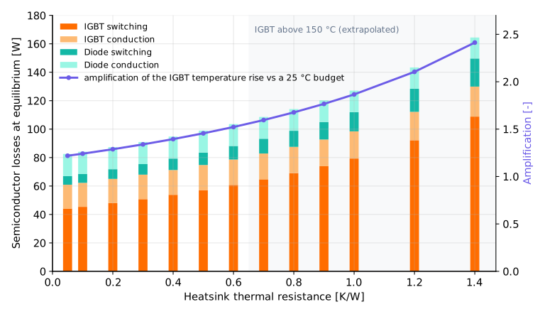 Figure A1 – Semiconductor losses at equilibrium for each heatsink (left axis) and amplification of the IGBT temperature rise compared with a budget frozen at 25 °C (right axis). In the grey area the IGBT junction is above 150 °C and the loss data are extrapolated.
With the same load current in every run, and within the range of the loss data (IGBT junction up to 150 °C, reached at 0.67 K/W): the total semiconductor losses grow from 82.5 W to 107.1 W, the IGBT switching loss from 44.2 W to 63.6 W, and the diode junction stays 18 K to 28 K below the IGBT junction. The semiconductor losses go from 1.4 % of the output power at 0.05 K/W to 1.7 % at the 0.51 K/W design point.
References
- Official SIMBA design example DC-DC Buck-Chopper (Thermal),
DesignExamples.Buck_Thermal_Tuple(), AESIM / Powersys. - SIMBA Python API documentation.
- Fuji Electric, IGBT Module Application Manual, Chapter 5 "Thermal Design" (MT5F43750), PDF.
- Semikron Danfoss, Application Note AN 20-001 "Calculating Junction Temperature Using a Module Temperature Sensor", 2024, PDF.
- Wintrich, A., Nicolai, U., Tursky, W., Reimann, T., Application Manual Power Semiconductors, 2nd ed., SEMIKRON International, 2015.
About the Authors
This technical study was run by SIMBA Assistant (Sophia), the AI agent of the SIMBA team, driving SIMBA desktop 2026.07.22 through Python, and reviewed by SIMBA Team.